This page discusses Power Over Ethernet (POE), including how it works, why it is used, its standards, its development, devices that utilize it, how to implement and monitor it, advantages and disadvantages of POE as seen below.
Power Over Ethernet (POE)
By using Ethernet data cables rather than standard electrical power cords and wiring to deliver the electrical current needed to run each device, Power Over Ethernet (POE) is a technique used to create wired Ethernet local area networks (LANs). Because data transmission and power-providing devices are coupled on the same RJ45 Ethernet connection, electricity can be transferred over network cabling.
The PoE standard was developed in 2003 to support gadgets like wireless access points. Prior to that, several businesses used a variety of proprietary PoE types to provide PoE capabilities. There are still some of these proprietary PoE devices in use today. Because these older, proprietary devices might not work with later standard PoE devices, PoE device installers need to find out where these devices are located. Today’s standard PoE devices make it easier and more flexible to deploy APs, even in ceilings that may be challenging to wire for electricity.
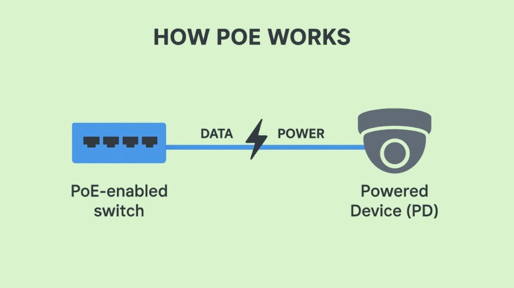
How PoE Works

Usually, a PoE system consists of two primary parts:
- Power Sourcing Equipment (PSE): A PoE-enabled switch or a PoE injector are examples of PSE devices that provide power. PoE functionality is integrated into the ports of a PoE switch. A PoE injector, sometimes called a midspan, is a tiny device that supplies power to a regular Ethernet cable before it is connected to a switch that isn’t PoE. PSEs can be utilized as midspans (power hubs used with existing non-powered Ethernet switches) or endspans (PoE-enabled Ethernet switches).
- Powered Device (PD): An IP camera, wireless access point, or VoIP phone are examples of devices that get power and data over an Ethernet cable. Wi-Fi routers, VoIP phones, security cameras, and other Internet of Things devices are a few examples.
To ascertain the power requirements, a PD negotiates with a PSE after connecting to it. This crucial safety feature guards against harm to non-PoE devices. To determine whether the connected device is a PD and what its PoE power class is, the PSE first provides low power signals and then watches for the return signal. After identification, power is sent based on the class that has been identified. Through Cisco Discovery Protocol (CDP) and Link Layer Discovery Protocol (LLDP) communications from the PD, the PSE continuously checks for changes in the power class and modifies the power level as necessary.
PoE is safer than high-voltage AC power since it uses a low voltage, usually less than 60V DC. PoE uses a technique known as “phantom power” to deliver electricity over the same wires used for data transmission without interfering with the data signal for Gigabit Ethernet (1000BASE-T) and faster standards that use all four pairs for data. With the data signal and power current kept apart, power current can enter an Ethernet data connection at the power source end and escape at the device end.
Also Read About How Data Flows Through The OSI Model And It’s Importance
Why use POE?
Designating Power over Ethernet in an installation has the following benefits:
- By reducing the time and expense associated with electrical power cabling installation Network cables can be installed practically anywhere and don’t need to be installed by a trained electrician.
- Since IP cameras and wireless access points are not connected to an electrical outlet, they can be positioned wherever they are most needed and swiftly moved if needed.
- The intelligent POE distribution system guards against improper installation, overload, and underpowering of network devices.
- When electricity is available on the network, network connection setup and installation are simple and efficient.
- POE power originates from a single, globally compatible source rather than a number of dispersed wall adapters. It can be controlled remotely to reset or deactivate devices, or it can be powered by an uninterruptible power source.
Different POE standards

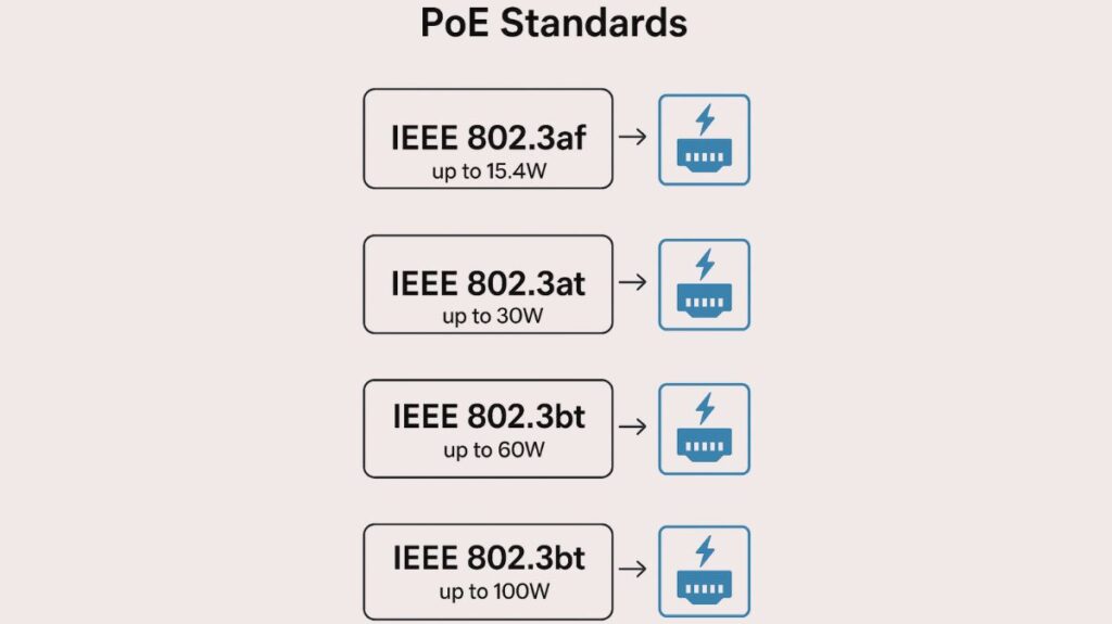
Different varieties of PoE, each with increasing power capacities, are defined by a number of standards created by the Institute of Electrical and Electronics Engineers (IEEE). Prior to IEEE standardisation, Cisco also created proprietary PoE versions. Backward compatibility with earlier standards is a feature of all new ones.
Type 1 (IEEE 802.3af), commonly referred to as PoE: The original standard was approved in 2003. At the PSE, it can supply up to 15.4 W of power per port; however, because of cable loss, only roughly 12.95 W is accessible at the powered device. It is appropriate for low-power devices like VoIP phones and static IP cameras and requires two wire pairs for power.
Type 2, sometimes referred to as PoE+ (IEEE 802.3at): This standard, which was ratified in 2009, allows the device to use up to 25.5 W at the PSE and up to 30 W per port. Additionally, it draws electricity from two wire pairs. This kind is utilised for more power-hungry gadgets including more potent wireless access points and pan-tilt-zoom (PTZ) cameras.
Type 3 (IEEE 802.3bt), sometimes referred to as 4PPoE/UPoE or PoE++: With 51 W available at the device, this standard allows up to 60 W per port at the PSE. To provide additional power, it makes use of all four pairs of wires in the Ethernet cable. Devices like building management sensors and video conferencing systems use it. Cisco introduced 60W UPOE in 2011 before IEEE 802.3bt.
Type 4 (IEEE 802.3bt), also known as High-Power PoE / UPoE+: IEEE 802.3bt Type 4 High-Power PoE/UPoE+ provides maximum power, 100 W per port at the PSE and 71.3 W to the device. In 2018, 802.3bt was modified to boost source power to 90W (Type 4). Laptops, huge screens, LED lighting, kiosks, AC units, and refrigerators can be powered. It powers several desk devices with a “single cable” workstation.
Power loss is taken into consideration over a maximum cable length of 100 meters for PoE. Type 3 (60W) and Type 4 (90W) PoE require at least Cat 5 cabling.
The development of PoE
In order to provide scalable and controllable power distribution to Cisco IP-telephony handsets, Cisco created and first provided a proprietary version of PoE in 2000.
PoE first employed unused pairs of the four twisted pairs of copper wires found in ordinary Category 5 (Cat 5) cable, simulating the way classic PSTN (public switched telephone network) landline phones work delivering 48V DC power over the same copper cabling used for communications.
To guarantee interoperability across a wider range of linked powered devices and power sourcing equipment, the Ethernet Alliance and IEEE began working to standardize PoE in 1999. The first of these standards, IEEE 802.3af, was approved in 2003 and stipulated that either data pairs (pins 1 and 2 or pins 3 and 6) or spare pairs (pins 4 and 5 or pins 7 and 8) must be able to carry the power.
Devices that use POE
The following devices that require 30 watts (W) or less of electricity can be used with POE:
- VoIP telephones
- IP cameras
- Audio over a network
- Robotic cameras that can tilt and zoom
- Liquid crystal displays and large televisions
- wireless access points
- VoIP, video phones, and IP
Implementing and Monitoring PoE
PoE can be incorporated into a network using:
- PoE switches: A network switch that has Power over Ethernet injection built in is known as a Power over Ethernet (POE) switch. The switch will automatically detect whether additional network devices are POE-compatible and turn on the power if they are simply connected to it as usual. POE switches are available to suit various applications, ranging from inexpensive unmanaged edge switches with a few ports to complex multi-port rack-mounted systems with advanced administration.
- Midspans (PoE injectors): Midspans, also known as PoE injectors, use an injector, which is a powered patch panel that sits between the PDs and an Ethernet switch. The PSE enables the cable to be routed to distant devices without obstruction and is frequently placed close to the switch. Midspans cannot transport electricity over data lines like Gigabit Ethernet connections since they are only permitted to use the spare pair of cables.
PoE transmits power in several modes:
- During 10BASE-T or 100BASE-TX transmissions, power is sent via the same cable pairs as data (Pins 1, 2, & 3, 6).
- Mode B (spare-pair power) transmits power via Pins 4, 5, 7, and 8.
- 4PPoE: All four Ethernet wires transfer power.
To install PoE, LAN designers must examine PD types and their power requirements, set a power budget for all connected PDs, verify switches have enough PoE-capable ports, and properly size PoE switch power supply to provide enough watts for the switch and attached PDs. Devices must be connected to PoE ports using normal wiring.
A “Mode” button on Cisco Catalyst switches frequently cycles through LED indications, such as a PoE LED, that show different statuses:
- Off: The PD is powered by AC or PoE is turned off.
- Green: PoE is operational and supplying electricity.
- Alternating Green-Amber: Because power supply would be greater than the switch’s capability, PoE is rejected.
- Amber: The port’s PoE has been turned off.
Advantages of PoE
PoE offers many advantages:
- Cost savings: Eliminating expensive electrical wiring and power outlets and reducing cable lines dramatically decreases installation costs.
- Flexible: Network cables can be used to deploy devices anywhere, even without power outlets. This makes them ideal for high-wall or ceiling equipment.
- Safety: PoE uses low-voltage DC power and smart protection mechanisms against overload, underpowering, and poor installation to eliminate high-voltage AC power dangers.
- Centralized Management and Reliability: A network closet may control electricity for all connected devices. This permits continuous operation with easier device resets, power usage monitoring, and a single UPS for outages.
- Simple Deployment: PoE transfers DC power over Ethernet, eliminating power bricks and saving space.
- Electricity enables network expansion by connecting and distributing.
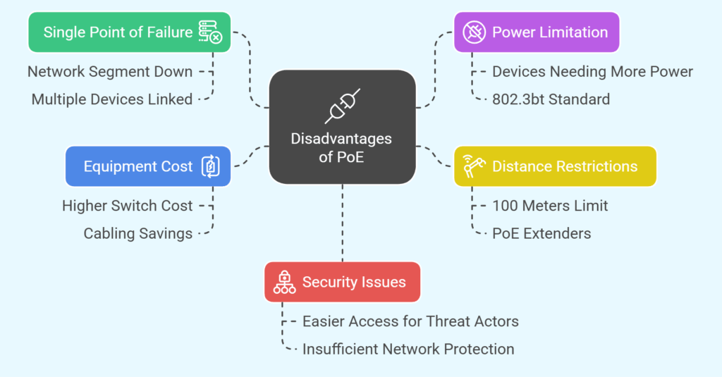
Disadvantages of PoE

PoE has many disadvantages despite its many advantages:
- Single Point of Failure: The entire network segment may go down if several devices are linked to a single PoE connection and that connection fails.
- Power Limitation: Higher PoE standards (802.3bt) are required for devices that need more than 30 W.
- Distance Restrictions: Unless PoE extenders are utilised, PoE power transmission is often restricted to 100 meters.
- Equipment Cost: PoE switches are more costly than conventional switches, however this is frequently compensated for by overall cabling savings.
- protection Issues: Threat actors may find it simpler to access PoE devices linked to the network if there is insufficient network protection.
