Intermediate System to Intermediate System

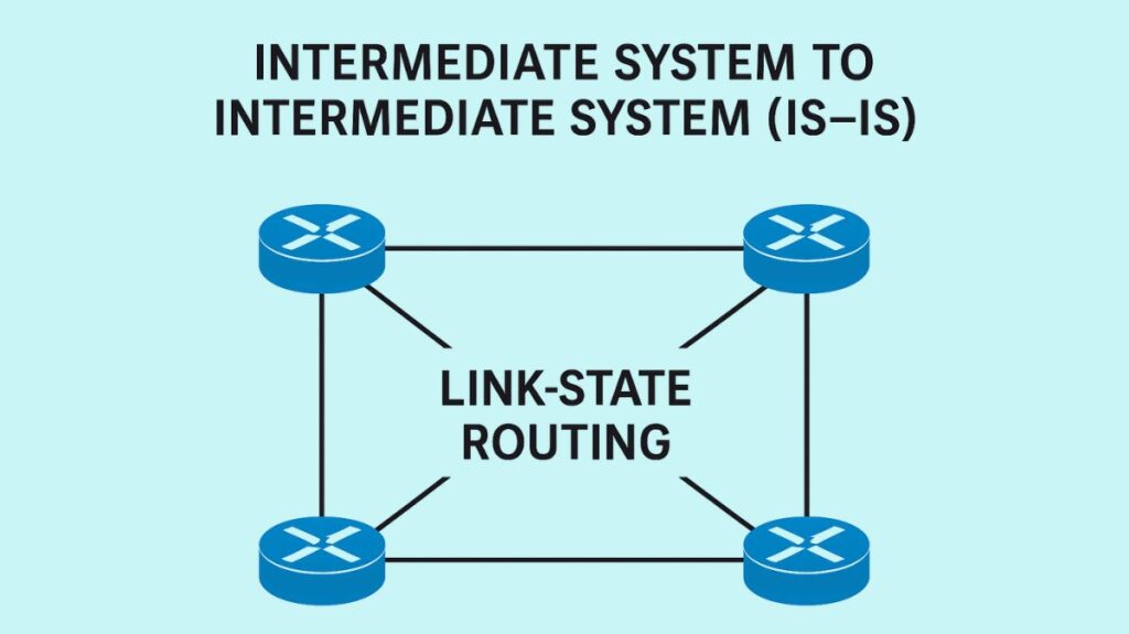
ISIS, or Intermediate System to Intermediate System (IS-IS), is a dynamic link-state routing system that is intended to effectively transfer data inside a computer network. By choosing the most efficient path for data across a packet-switching network, it does this.
General Definition and Classification
Purpose: Network devices, often known as routers or intermediate systems, use Intermediate System to Intermediate System to help them decide how best to forward data. In addition to creating an extensive network map, it employs an algorithm to determine the best paths.
Protocol Type: One type of link-state routing protocol is Intermediate System to Intermediate System. The way it works is by flooding a network of routers with connection state information.
Interior Gateway Protocol (IGP): An Internet service provider (ISP) or a big enterprise network are examples of Autonomous Systems (AS) that are intended to use it. This protocol is known as an Interior Gateway Protocol (IGP). When it comes to routing between autonomous systems, this is in contrast to external gateway protocols like Border Gateway Protocol (BGP).
OSI Model: According to ISO/IEC 10589:2002, Intermediate System to Intermediate System is an international standard that is part of the Open Systems Interconnection (OSI) reference design. Because it is an OSI protocol that operates at Layer 2, or the data connection layer, it is not reliant on IP addresses.
Industry Standard: For big service provider network backbones, Intermediate System to Intermediate System was regarded as the de facto standard by 2005. Cisco actively participates in and helps improve the IS-IS working group of the IETF.
You can also read How Does Distance Vector Routing Work And Examples
History and Evolution
Origin: A group at Digital Equipment Corporation created the protocol as part of DECnet Phase V, and in 1992, ISO standardized it as ISO 10589 for use in communication between Intermediate Systems, which are network devices.
Original Purpose: Connectionless-mode Network Service (CLNS), an OSI protocol stack created by ISO, was first intended to facilitate datagram routing.
Integrated IS-IS: Datagram routing in the Internet Protocol (IP), the network-layer protocol of the global Internet, was later supported by IS-IS. It can route several network protocols, such as IP, ISO routing, or a mix of the two. This version is known as Integrated Intermediate System to Intermediate System or Dual IS-IS.
How IS-IS Works

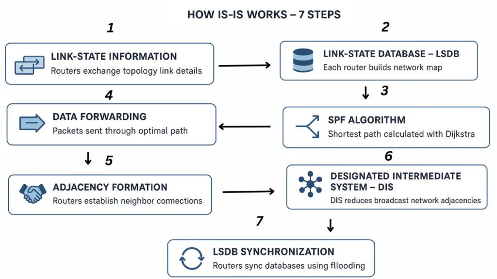
Link-State Information: For the purpose of exchanging information on the network topology and their directly associated links, IS-IS routers exchange Link State Packets (LSPs).
Link-State Database (LSDB): Every Intermediate System to Intermediate System router individually aggregates the deluged network data to create a Link-State Database (LSDB). The topology of the network is fully mapped in this database.
Path Calculation (SPF Algorithm): Similar to the OSPF protocol, Intermediate System to Intermediate System determines the optimal (shortest and most effective) path to every destination throughout the network using Dijkstra’s Shortest Path First (SPF) algorithm.
Data Forwarding: Data packets are forwarded to their intended locations by routers using the computed pathways.
Adjacency Formation: Routers use Intermediate System to Intermediate System Hello PDUs (IIHs) to create adjacencies, or neighbour connections. Adjacencies may be point-to-point or broadcast.
- The Hello interval times do not have to match, in contrast to OSPF.
- A handshake mechanism (two-way or three-way for P2P links) is a part of neighbour relationships.
- Two-way handshake mechanism: A routing device creates a neighbour relationship and unilaterally declares a peer Up after receiving a Hello packet from a peer.
- Three-way handshake mechanism: Similar to the establishment of a broadcast neighbour relationship, this mode establishes a neighbour relationship by sending P2P Intermediate System to Intermediate System Hello PDUs three times.
Designated Intermediate System (DIS): To represent a collection of Intermediate Systems on broadcast segments (LANs, for example), a DIS is chosen. In a hub-and-spoke architecture, this minimizes the amount of adjacencies because routers only establish adjacencies with the DIS, which subsequently relays LSPs to lower-level routers. The router designated as the DIS is the one with the highest priority and System ID. An example of a pseudonode is a DIS.
LSDB Synchronization: By means of LSP flooding, LSDBs are synchronized. Sequence numbers are assigned to LSPs, with updated LSPs having higher sequence numbers. Database consistency is ensured by summarizing and requesting missing LSPs using Complete Sequence Number PDUs (CSNPs) and Partial Sequence Number PDUs (PSNPs).
You can also read What Is EIGRP Enhanced Interior Gateway Routing Protocol?
Key Characteristics and Features
Scalability: Large service provider and enterprise networks like Intermediate System to Intermediate System because of its effective flooding mechanisms and hierarchical design, which makes it very scalable.
Hierarchical Design: Level 1 (L1) and Level 2 (L2) sections are part of its two-level hierarchical design support.
- Level 1 (L1) routers are internal to an area and maintain an LSDB only for that area. They forward traffic destined outside their area to a Level 1/Level 2 router.
- Level 2 (L2) routers form the backbone of the Intermediate System to Intermediate System network, route traffic between areas, and maintain a separate L2 LSDB for inter-area routing. L2 routers must be contiguous to ensure a fully routable backbone.
- Level 1/Level 2 (L1/L2) routers are boundary routers that participate in both intra-area (L1) and inter-area (L2) routing, maintaining separate L1 and L2 LSDBs. They advertise their boundary status using the Attached Bit (ATT) in their L1 LSP, causing L1 routers to add a default route to them.
Protocol Agnostic / Flexibility: Because it can transport different kinds of reachability data and is not restricted to IP routing, Intermediate System to Intermediate System is “future-proof” and appropriate for complicated networks.
Fast Convergence: Intermediate System to Intermediate System minimizes service interruption by swiftly adjusting to changes in network topology because it is a link-state protocol.
IPv6 Support and Multi-topology: Specific TLVs (TLV 232 for IPv6 interface address and TLV 236 for IPv6 reachability) and a Network Layer Protocol Identifier (NLPID) of 0x8E are used by Intermediate System to Intermediate System to enable IPv6 routing information. Even when topologies do not overlap, IS-IS can prevent traffic black holes by calculating distinct SPF trees for IPv4 and IPv6 with its multi-topology capability.
Authentication: Simple password and MD5 authentication are supported by Intermediate System to Intermediate System, and per-level or per-interface authentication is feasible. Increasing sequence numbers in IIHs is another method it takes to defend against replay attacks.
BFD Support: When combined with IS-IS, Bidirectional Forwarding Detection (BFD) can detect faults in less than a second, providing a low-overhead substitute for shortening Hello packet intervals.
Hostname Resolution: A Type Length Value 137 (TLV 137) field that contains a human-readable hostname linked to a Network Entity Title (NET) can be carried by LSPs with IS-IS’s built-in hostname resolution.
Attribute Bits in LSPs: In their header, LSPs include an 8-bit attribute block that contains the following:
- P bit (Partition repair): If a partitioned L1 region may be mended (connected together) over L2 area, it is indicated by the partition repair bit, which is the eighth bit. Generally speaking, partition repair is not supported by modern Intermediate System to Intermediate System implementations, and the P bit is not set.
- ATT bit (Attached bit): A Level-1-2 router creates it to show if the original router is connected to additional regions. A Level-1 router establishes a default route to the Level-1-2 router in order to route data to other locations when it gets a Level-1 LSP from a Level-1-2 router that has the ATT bit set.
- OL bit (Overload bit): Even though the network is still flooded with LSPs that have the overload bit set, the routes that go via the overloaded router are not determined by them. That is, other routers disregard the router when calculating SPF once the overload bit has been set on it, with the exception of the router’s direct routes.
- IS type bits: Choose the IS type of the originator (L1, L2, or L1/L2).
Wide Metrics: At first, IS-IS was limited by metrics (63 for interface, 1023 for path). New TLVs (TLV 22 and TLV 135) were added to Wide Metrics to handle larger networks, enabling link metrics of up to 16.7 million and path metrics of up to 4 billion.
Intermediate System to Intermediate System Addressing and NET
ISO Network Address: In contrast to IP-based systems, Intermediate System to Intermediate System does not rely on Layer 3 IP addresses. ISO Network Addresses are used instead.
- Network Service Access Point (NSAP): Every distinct connection point, such as a router port, has an NSAP allocated to it.
- Network Entity Title (NET): A NET is issued to individual Intermediate Systems (routers); it is comparable to an NSAP but without the Selector field set.
NET Structure: The NSEL field, System ID, and Area make up a NET.
- Area: It has a configurable length (1–13 bytes) and consists of an Area ID and an Address Family Identifier (AFI). In particular, “private address space” is represented by AFI 49.
- System ID: It’s usually advised to assign the six-byte file to a distinct IPv4 address from one of the router’s loopback interfaces.
- NSEL: Since only NSAPs use it, it is one byte long and must be zero for routers.
For example, in “49.0100.1921.6821.1138.00”:
49is the AFI (representing private address space).0100is the Area ID.1921.6821.1138is the System ID (six bytes long).00is the NSEL (one byte, which must be zero for routers).
You can also read Advantages Of Routing Information Protocol And How RIP Works
IS-IS Packet Types

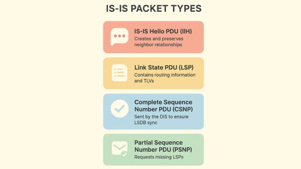
IS-IS Hello PDU (IIH): Used to create and preserve ties with neighbours. Point-to-Point (P2P, PDU type 17), LAN L1 (PDU type 15), and LAN L2 (PDU type 16) connectivity come in several varieties.
Link State PDU (LSP): Type-length-values (TLVs) and other routing information are included. There are three IDs in the LSP header: System, Pseudonode, and Fragment.
Complete Sequence Number PDU (CSNP): A list of LSP IDs, sequence numbers, and checksums are sent out by the DIS on broadcast networks on a regular basis (every 10 seconds by default) to guarantee LSDB synchronization.
Partial Sequence Number PDU (PSNP): When a router receives a CSNP and discovers a discrepancy in its LSDB, it sends a message asking for particular LSPs. Additionally, PSNPs can serve as acknowledgements for received LSPs on P2P links.
IS-IS Path Selection
When an Intermediate System to Intermediate System router has the same prefix from external/internal sources or from various level databases (L1, L2), there is a particular order of preference for path selection, going from most favoured to least desired:
- L1 intra-area with internal metric.
- L1 external with internal metric.
- L2 intra-area with internal metric.
- L2 external with internal metric.
- Inter-area (from L1 to L2) with internal metric.
- Inter-area external (from L1 to L2) with internal metric.
- Inter-area (from L2 to L1) with internal metric.
- Inter-area external (from L2 to L1) with internal metric.
- L1 external with external metric.
- L2 external with external metric.
- Inter-area external (from L1 to L2) with external metric.
- Inter-area external (from L2 to L1) with external metric.
Other Uses and Extensions
Shortest Path Bridging (SPB): The control plane of SPB is based on Intermediate System to Intermediate System, which is extended with new TLVs to allow equal-cost multipath routing between Ethernet switches.
Segment Routing (SR-MPLS / SRv6): For Segment Routing MPLS (SR-MPLS) and Segment Routing IPv6 (SRv6), Intermediate System to Intermediate System has been expanded with new TLVs to advertise topology, prefix, Segment ID (SID), and label information.
You can also read What is Link State Routing Protocols And How It Works
Advantages and Limitations
Advantages: Fast convergence, resilient, adaptable in managing numerous network protocols, favoured in big ISP backbones, highly scalable and dependable, and capable of providing simpler configuration in homogenous environments in contrast to OSPF’s multi-area structure. It has considerable extensibility with its TLV packet structure.
Limitations: May have a high learning curve because of its link-state structure and specialized language. Large networks may be too big for the default metric constraints (6-bit), however “wide metrics” are available. In L1 (stub) locations, suboptimal routing may take place if a better path via a different L1/L2 router is available. Workarounds are necessary since it lacks native support for Non-Broadcast Multi-Access (NBMA) networks.
IS-IS Comparison with OSPF
Both employ the SPF algorithm as link-state IGPs, although there are several significant distinctions:
Layer of Operation: The data link layer protocol is used by Intermediate System to Intermediate System, while the IP-layer protocol is used by OSPF.
Extensibility: Because of its TLV packet format, IS-IS is more extensible than OSPF, which usually calls for new LSA types or protocol versions (such as OSPFv3 for IPv6). For example, IPv6 support just requires TLV extensions.
Application Scope: Major networks, including major ISP networks, are best suited for IS-IS, but OSPF is typically better suited for medium-sized networks (hundreds of devices).
Area Division: IS-IS separates areas by router, while OSPF separates areas by interface.
History: OSPF originated from a previous iteration of the IS-IS protocol.
All things considered, IS-IS is a reliable, incredibly scalable, and adaptable link-state routing protocol that was first developed for CLNP routing in the OSI world. It has since developed into Integrated Intermediate System to Intermediate System to efficiently support IP routing (IPv4 and IPv6) in big, complicated networks, especially those of service users.
You can also read What Is OSPF Open Shortest Path First? Advantages Of OSPF
