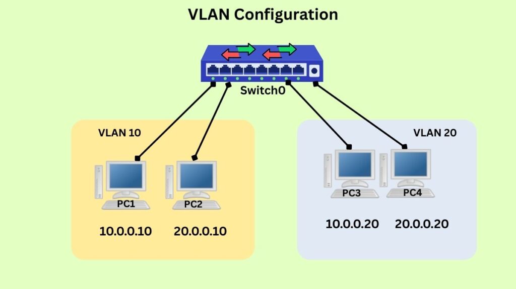
Basic VLAN configuration

The technique of splitting a physical network into several logical networks is known as VLAN (Virtual Local Area Network) setup. A single physical network can operate as multiple separate broadcast domains to this logical segmentation.
The following are the main objectives of VLAN configuration:
- Enhancing safety.
- Lowering broadcast traffic in order to improve performance and efficiency.
- Making network administration easier.
Important VLAN Configuration Concepts
Awareness VLAN setup requires an awareness of several key ideas:
- VLAN ID: A special number that is assigned to every VLAN, usually 1-4094.
- “Sales” or “HR” are examples of descriptive names that are assigned to each VLAN.
- Access ports are switch ports used to connect endpoints, such as PCs or printers, and are part of a single VLAN. The VLAN assigned to an access port is linked to the traffic that enters that port.
- Trunk Ports: These ports are set up to concurrently transport traffic for several VLANs. Usually, they are employed to link switches to routers or to one another. Trunk ports determine which VLAN each Ethernet frame belongs to by using tagging methods like IEEE 802.1Q.
- The procedure that enables communication between devices in various VLANs is known as inter-VLAN routing. Devices in separate VLANs are by default unable to communicate with one another. Typically, a Layer 3 device such as a router or Layer 3 switch is needed for inter-VLAN routing.
General Process for VLAN Configuration
Although particular commands may differ according on the manufacturer of the network equipment (e.g., Cisco, Juniper, HP), the general processes for configuring VLANs are as follows:
Plan Your VLANs
- Create a list of VLAN groups according to network requirements (e.g., IT, HR, Voice).
- Give each group a distinct VLAN ID (a number) and a meaningful name.
Create VLANs on the Switch
- Start by gaining access to the switch, usually by Telnet, SSH, or console.
- Go into global configuration mode (e.g.,
Switch# configure terminal) after entering privileged EXEC mode (e.g.,Switch> enable). - Give the VLAN a name and define its ID to create it.
Switch(config)# vlan 10andSwitch(config-vlan)# name Salesare examples of Cisco CLI commands.- As an alternative, you can use a GUI by going to the VLAN area and entering the name and ID.
Configure Switch Ports
For End-User Devices (Access Ports):
- Choose the particular interface (
Switch(config)# interface fa0/1, for example). Switch(config-if)# switchport mode accessis an example of setting the port mode to access.- You can assign the port to the VLAN of your choice by using the syntax Switch(config-if)# switchport access vlan 10.
Ports Fa0/1 through Fa0/5 may be allocated to VLAN 10 (Sales Dept.) in an example VLAN table.
For Connecting Switches (Trunk Ports):
- Set up ports so that several tagged VLANs can go between switches. Usually, protocols such as 802.1Q are used to tag Ethernet frames.
- Cisco CLI Example:
interface <interface ID>followed byswitchport mode trunkand optionallyswitchport trunk allowed vlan.
Configure Inter-VLAN Routing (if needed)
A router or Layer 3 switch needs to be set up to manage the various VLANs if communication between devices in different VLANs is necessary.
Verifying VLAN Configuration
It’s critical to confirm that everything is operating as planned after configuration. Typical techniques for verification consist of:
show vlan brief(or similar command): A list of all configured VLANs, along with their names and the access ports allocated to them, is shown by this command. It is a rapid method of verifying port assignments and VLAN formation.
show interfaces <interface_id> switchport: This command gives comprehensive details on the configuration of a particular switch port, such as whether it is trunking, whose VLAN or VLANs it belongs to, and its mode (access or trunk).
show interfaces trunk: This command verifies which VLANs are permitted to use trunk ports and are actively trunking over that link.
ping command
- Verify that all of the devices in the same VLAN are connected. If successful, it means that Layer 3 addressing within the VLAN is sound and that the VLAN is set up appropriately at Layer 2.
- Check if devices in various VLANs may connect to one another (if inter-VLAN routing is configured). This confirms that traffic between VLANs is being routed correctly by the router/Layer 3 switch.
- Isolation can be verified by trying to ping a device in a separate VLAN that shouldn’t be available (because of firewall restrictions or poorly configured routing) and seeing a “Destination Host Unreachable” or timeout.
Also Read About Cisco Basic Switch Configuration Commands step by step guide
Packet Sniffing
You can use a packet sniffer, such as Wireshark, to view network activity on a device that is part of a VLAN. This can assist in verifying that traffic is appropriately tagged (on trunk ports) and that broadcast traffic is contained within its VLAN.
Best Practices
- Think about utilising distinct VLANs for data and voice traffic: to give voice traffic priority in order to improve quality.
- Using descriptive VLAN names facilitates management.
- VLAN 1 is frequently the default and may have security problems, therefore avoid using it for user data. Make a distinct management VLAN.
- Modify the trunk ports’ native VLAN: To prevent VLAN hopping attacks, avoid using VLAN 1 as the native VLAN on trunk links.
- Logically divide traffic: Assign devices to departments or functions rather than to physical locations.
- Keep a record of your VLAN setup: Keep track of your VLAN allocations and network diagrams.
- Put firewall rules or access control lists (ACLs) into action: to improve security by managing traffic flow between VLANs.
Also Read About Network Switch Benefits And Features of Network Switch
Example VLAN Table
| VLAN ID | VLAN Name | Purpose | Ports Assigned |
|---|---|---|---|
| 10 | Sales | Sales Dept. | Fa0/1 – Fa0/5 |
| 20 | HR | HR Dept. | Fa0/6 – Fa0/10 |
| 30 | IT | IT Dept. | Fa0/11 – Fa0/20 |
