What is Inter VLAN Routing

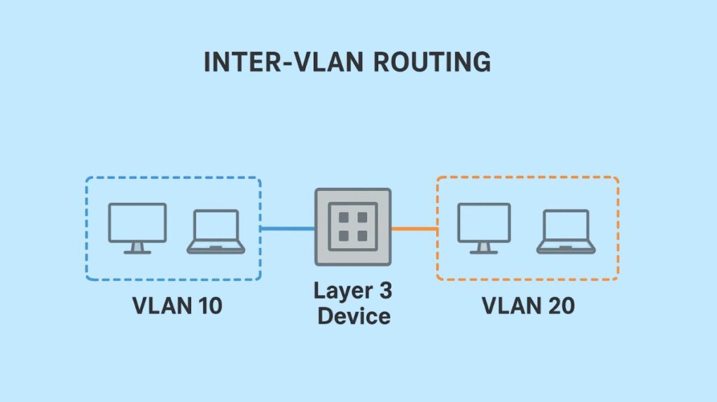
Inter-VLAN Routing is the process that allows devices in different Virtual Local Area Networks (VLANs) to communicate with each other. By default, hosts within the same VLAN can communicate freely, as they belong to the same broadcast domain. However, Layer 2 switches, by their nature, do not forward frames between different VLANs. Therefore, a Layer 3 device is essential to route IP packets between these logically separated networks.
Generally, distinct IP subnets are linked to VLANs. IP packets must be sent to the device’s local router, which serves as the default gateway, in order to reach hosts in a different subnet.
Why Inter-VLAN Routing is Necessary
Network segmentation, which is the main purpose for VLANs, has various advantages, such as increased security, greater performance due to less broadcast traffic, and more effective network management. Devices from several VLANs must frequently communicate with one another in the majority of real-world situations. Inter-VLAN routing takes care of this requirement by:
Enabling Communication: Permitting data communication across devices that belong to distinct logical groupings (such as the finance and engineering agencies).
Facilitating Shared Resources: Granting users in several VLANs access to shared resources, such as printers, file servers, and centralized DHCP/DNS servers, which may be situated on a different VLAN.
Enhancing Security and Access Control: It also offers a Layer 3 border, allowing administrators to use access control lists (ACLs) to limit and manage traffic flow between VLANs, so enhancing network security while permitting essential communication.
Supporting Scalability and Network Design: Makes it easier to design and maintain networks as a company expands, enabling effective communication and logical segmentation without requiring physical network reconfiguration.
Enabling Specialised Applications: In order to guarantee Quality of Service (QoS), applications such as Voice over IP (VoIP) need distinct VLANs for various types of traffic.
Load Balancing and Virtualization: A key component of network virtualization, it can be used to divide traffic among VLANs.
How Inter VLAN Routing Works

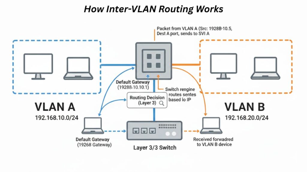
Inter-VLAN routing is based on the fundamental idea of using a Layer 3 device, like a Layer 3 switch or router. The Layer 3 interface on the routing device corresponding to VLAN A is the first place traffic is sent when a device in one VLAN (e.g., VLAN A) wishes to send data to a device in another VLAN (e.g., VLAN B). The Layer 3 device then examines the packet, decides on a routing strategy based on the destination IP address, and forwards the packet to the appropriate interface for VLAN B, thereby directing traffic between the two VLANs.
Inter VLAN Routing Methods

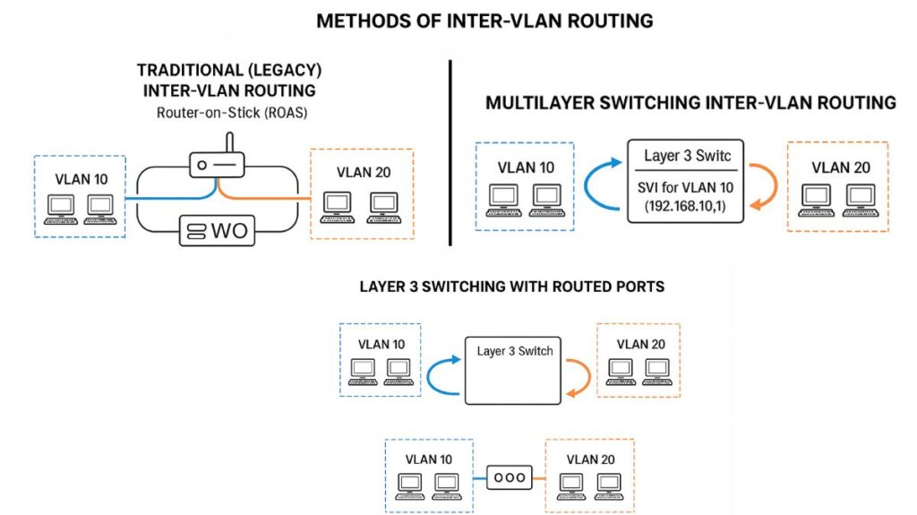
Implementing Inter-VLAN routing can be done in three main ways:
There are three main approaches to inter-VLAN routing implementation:
- Traditional (Legacy) Inter-VLAN Routing
- Router-on-a-Stick (ROAS)
- Multilayer Switching (Layer 3 Switch)
Traditional (Legacy) Inter-VLAN Routing
This approach necessitates several physical interfaces on the switch and router. Every router interface has an IP address given to it within the subnet of its own VLAN on the switch. Although this method is simple, networks with numerous VLANs cannot use it since it rapidly uses up physical router interfaces.
Router-on-a-Stick (ROAS)
A popular technique called Router-on-a-Stick (ROAS) routes traffic between several VLANs using a single physical router interface that is set up with several logical subinterfaces. This physical interface is connected to a neighbouring switch’s VLAN trunk.
Key Concepts for ROAS:
Subinterfaces: Each VLAN that requires routing has its own virtual interface, or subinterface, created by the router. Every subinterface has an IP address and mask assigned to it for the subnet of that VLAN.
VLAN Trunking: The router and Layer 2 switch link have to be set up as a trunk. This trunk uses VLAN tagging to transport traffic for several VLANs over a single physical link. IEEE 802.1Q, which adds a 32-bit header with a 12-bit VLAN ID to the Ethernet frame, is the most widely used trunking protocol. Cisco also supports their proprietary Inter-Switch Link (ISL) protocol.
Native VLAN: Untagged traffic on 802.1Q trunks has its own native VLAN. VLAN 1 is the default. The native VLAN should be changed to an unused VLAN as a security best practice. The encapsulation dot1q vlan-id native command can be used to setup the router on a subinterface if it must route packets for the subnet of the native VLAN. Alternatively, the IP address can be set on the physical interface itself. VLAN hopping is a security flaw that occurs when native VLANs on a trunk are mismatched, causing transmissions to “hop” between VLANs.
ROAS Configuration Steps on a Router (Example for R1 with Gig0/0):
- Activate the physical interface:
interface g0/0followed byno shutdown. - Create subinterfaces for each VLAN:
interface g0/0.vlan_id(e.g.,interface g0/0.1 0). - Configure encapsulation:
encapsulation dot1q vlan_id(e.g.,encapsulation dot1q 10). Usenativekeyword for the native VLAN. - Assign IP address and subnet mask:
ip address ip_address subnet_mask. - Repeat for all VLANs that need routing.
ROAS Verification Commands:
show ip route.show vlans.show ip interface brief.
Multilayer Switching Inter-VLAN Routing
Layer 2 switching and Layer 3 IP routing are combined in multilayer switches (also known as Layer 3 switches) into a single device. Because of its high packet processing rates and efficiency, this method is frequently chosen in bigger LANs.
Two primary kinds of Layer 3 interfaces for inter-VLAN routing are supported by Layer 3 switches:
Switched Virtual Interfaces (SVIs): For inter-VLAN routing, these virtual VLAN interfaces are utilized. In order for the switch’s routing logic to connect to a VLAN, an SVI offers a Layer 3 interface inside of it. The Layer 3 switch keeps an IP routing table with connected routes off these SVIs, and it functions similarly to a router interface with an IP address and mask.
- SVI Configuration Steps:
- Enable IP routing:
ip routing. - Create a VLAN interface:
interface vlan vlan_id(e.g.,interface vlan 10). - Configure IP address and mask:
ip address ip_address subnet_mask. - Enable the interface (if necessary):
no shutdown.
- Enable IP routing:
- SVI Verification:
show ip route(to see connected routes),show interfaces vlan vlan_id.
Routed Ports: These are actual switch ports that are set up to function more like Layer 3 router interfaces than Layer 2 switch ports. Bypassing Layer 2 switching logic, frames on a routed port immediately initiate Layer 3 routing logic, which includes header stripping and routing decision-making. With the no switchport command, a physical interface can be set up as a routed port.
- Routers with integrated switch ports can also implement routing between VLANs on those ports using SVI interfaces, similar to a Layer 3 switch. The switch ports are assigned to VLANs (e.g.,
switchport access vlan 10), and then SVIs are created for those VLANs on the router’s internal routing engine.
Advantages of Inter VLAN Routing

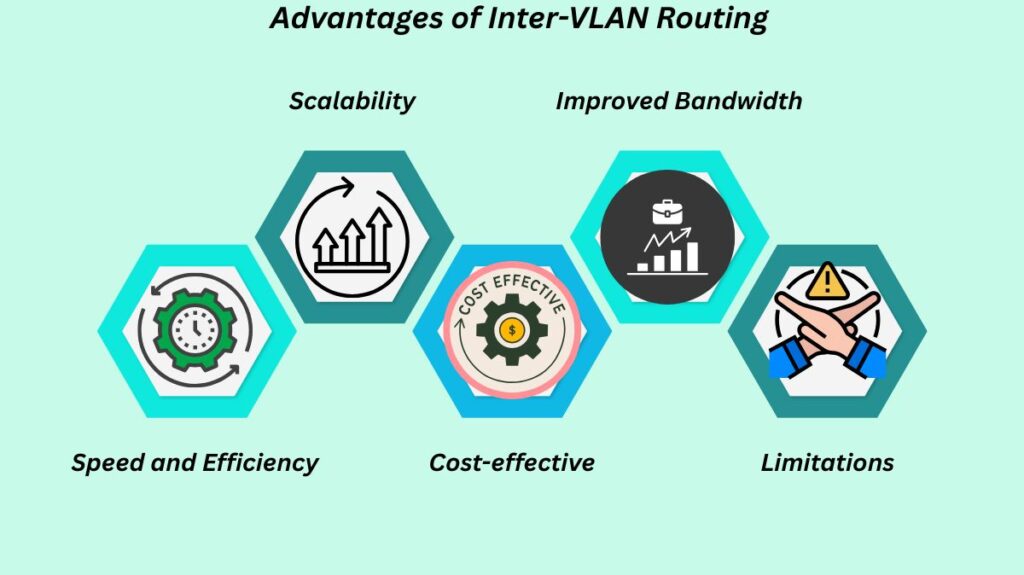
Speed and Efficiency: When routing is done in hardware, throughput is higher and latency is lower than using ROAS.
Scalability: Adds more VLANs with ease and without requiring major adjustments to the network structure.
Cost-effective: Does Layer 2 and Layer 3 tasks without requiring a separate external router.
Improved Bandwidth: Uplink ports can make use of EtherChannels to boost bandwidth and offer link redundancy.
Limitations: Originally more costly than employing a separate router for smaller networks. Compared to dedicated routers, Layer 3 switches may have fewer routing options. In big networks, configuration might be complicated. The failure of the Layer 3 switch disrupts all inter-VLAN traffic.
Key Concepts in Inter-VLAN Routing
VLANs (Virtual Local Area Networks): Divide a physical network logically into smaller broadcast areas.
Trunk Link: Traffic carrying for several VLANs via a network link (for example, between a switch and a router or another switch).
802.1Q Tagging: A technique that enables many VLANs to use a single trunk link by adding a tag to Ethernet frames to indicate which VLAN the frame belongs to.
Sub-interface: The router may manage traffic for many VLANs by creating a logical interface on its physical interface (used in Router-on-a-Stick).
Switch Virtual Interface (SVI): A virtual interface on a Layer 3 switch that serves as the VLAN’s default gateway and represents a VLAN with Layer 3 routing capabilities.
Default Gateway: The IP address of the Layer 3 switch or router interface that is used by devices in a VLAN to transmit traffic to other VLANs or networks.
Troubleshooting Inter-VLAN Routing
The following should be taken into account when resolving inter-VLAN communication problems:
VLAN Assignment: Make sure that the source and destination ports are appropriately allocated to the corresponding VLANs.
Trunk Configuration: Make sure both trunk ends’ native VLANs match and that trunk links are configured correctly.
Default Gateway: Verify that the VLAN interface IP address is set up as the default gateway on the devices.
Subnet Masks: Make that the subnet masks on the source and destination devices match.
IP Routing: Ensure ip routing is enabled on the Layer 3 switch or router.
Routes: Verify that the Internet gateway router’s IP address is correctly pointed to by the Layer 3 switch’s default route (such as the Catalyst 3850) for external connectivity, and that the gateway router has routes to the internal networks.
Switches from the Cisco Catalyst series, including the 3850 and 4500, are frequently used to configure Inter-VLAN routing since they offer both Layer 2 and Layer 3 features.
